
1. Introduction.
For all electronic equipment there are certain protective measures that can be taken to prevent alterations in the power supply causing damage to components that will have an impact on the equipment’s operation. However, like all protective measures, there are limitations on their effectiveness.
Electricity companies must ensure that the voltage and frequency of the signal they supply are in perfect condition.
However, there are many reasons why undesired effects can alter these nominal values.
The main effects of damage caused to computer equipment by electricity are as follows:
- Slow fluctuations in voltage
- Rising and falling voltage
- Overvoltage and short impulses
- Frequency changes
2. Causes of electronic failures
There various causes of these undesired effects:
- Power company switching.
- Performance of network protection devices.
- Short-circuits.
- Input/output of inductive loads.
- Switching of powerful machinery.
- Alterations caused by equipment connected to the same network.
- Electrostatic discharge (ESD).
- Energy transfers (generators).
- Natural causes, mainly lightning.
A direct lightning strike near a power line has different effects on the line that can cause overvoltage in the line and in the grounding equipment to which it is connected. The current generated by a typical stroke of lightning can reach values between 5 and 150 KA (Kilo amperes) with a rise time of 0.1 to 5 ms (milliseconds) and 20-300 ms of total duration.
If these levels of disturbance reach the input of our electronic equipment they cannot be assumed by the installed protection components. To put it simply, if we have a fuse at the input to the power supply that takes 1 millisecond to cut off the supply when there is a power surge, by the time the protection system takes effect, the surge has already reached the internal components, destroying them and rendering the equipment inoperative.
Electrostatic discharges are a major cause of damage to electronic equipment, and while the effects are less “spectacular” than those caused by thunderstorms, they are no less harmful. Some informal data shows that between 8 and 33% of “lost” equipment was caused by electrostatic discharge.
The phenomenon of electrostatic discharge occurs when two bodies at different electrical potentials come into contact and during that contact their potentials are evened out, transferring electrons between them. This electron transfer is itself an electrical current. To get an idea of how harmful it can be to brush up against someone in our path, note that: walking on carpeting we can reach voltages as high as 35,000V, and when we walk on tiles it is 12,000V, a plastic bag can have up to 20,000V and when we pick it up the electrostatic discharge mentioned above occurs.
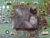
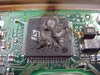
Some examples of electronic failures :

3. Measures
There are different measures that can be taken to protect against these types of failures:
One of the good things about electrical storms is that they are usually predictable and we can disconnect our computer equipment before they happen. We say disconnect because it is not enough to simply turn them off, since a power surge can still run through the cables connected to the equipment, destroying the source and any other components it may encounter along the way.
If for some reason the equipment needs to be connected or running at all times, a voltage limiter or UPS (Uninterrupted Power Supply) can be used.
3.1. Voltage limiters
A limiter or clipper is a circuit that uses resistors and diodes to eliminate unwanted voltage before it reaches a certain point on a circuit. A limiter can be used to ensure that only positive or only negative voltage reaches a certain circuit. However, this can also be done with a single diode forming a half-wave rectifier. We will focus on the type of limiter that prevents certain voltage that could be harmful to the circuit from reaching the circuit.
Unpolarised clipper
Imagine that in a case such as the one in the figure, we do not want voltages higher than 0.7 V, whether positive or negative, to reach the circuit we are protecting (in this case the element being protected is the load resistor LR). By mounting the two diodes and current limiting resistor as shown in the figure, any voltage greater than 0.7 V or lower than -0.7 V is clipped by the diodes. These 0.7 V are the potential barrier of the diode. Bear in mind that the limiting resistance is much lower than the load resistance. Therefore the voltage dropped onto the limiting resistor is negligible and can be disregarded.
Although the limiting resistor may seem unnecessary, it is important to understand that it is actually an essential part of the clipper. If it were not connected when one of the diodes was polarized directly (the two diodes cannot be directly polarized at the same time), it would start to conduct the electricity without control and it would be destroyed. As its name suggests, the function of the limiting resistor is to limit the current running through the diodes.
This way, if the input voltage were to exceed 0.7 V for any reason, diode D1 would be polarized directly and would clip the excess voltage. Likewise, if the input voltage were to fall below -0.7 V, diode D2 would be polarized directly and would clip the excess voltage that could damage the load.
Polarized clipper
Often we do not want the diodes to clip the input voltage at 0.7 V or -0.7 V. For example, maybe we want the input voltage not to exceed 10 V or fall below -10 V (these are random voltages, we can choose the ones we want). If this is the case, we cannot use the circuit described above because we now need a polarized limiter. The only difference between the previous limiter and this one is that in this case we will polarize the diodes with batteries so that a voltage greater than 0.7 V is necessary for the diodes to be directly polarized.
If we do not want the voltage in the load to be greater than 10 V or lower than -10 V, we will mount the following circuit.
Let’s see how the circuit works:
When the input voltage is within normal limits, i.e. between 10 V and -10 V, neither of the diodes does anything.
Once the voltage exceeds 10.7 V (10 V for the battery plus 0.7 V for the diode’s potential barrier), diode D1 is directly polarized and begins to conduct, which prevents the voltage in the load from increasing.
If the input voltage falls below -10.7 V, diode D2 is polarized directly and begins to conduct, which prevents the voltage from dropping to dangerous levels.
Note that instead of batteries, we could also connect reverse polarized zener diodes whose zener voltage is equal to that of the batteries. The two batteries or zener diodes do not have to have the same potential; it all depends on the desired voltage levels of the protected circuit. It is very important to note that, in the latter case in which we want to clip the positive and negative half-cycle differently, we must ensure that the second source is greater than the first. The first cannot be greater than the second because in this case if both diodes were closed, which can happen if (Vi-I.Rlim)> E1 (and therefore if E1> E2, (Vi-I .Rlim)> E2), then both diodes would be directly polarized or short-circuited and E1 would try to supply its power to E2, in which case the battery would be destroyed.
3.2 UPS

A UPS (Uninterruptible Power Supply) is a device with a high-capacity battery that can provide power to all of the electronic devices connected to it if there is a blackout. Another of its functions is to regulate the flow of electricity, controlling the rises and falls of current and voltage in the mains. They are connected to equipment called critical loads, which can be medical, industrial and/or computing equipment. As discussed above, this type of equipment must always have power supply and the power must be of high quality due to the need to remain operational at all times without failures (surges or dips).
Direct Current UPS
The loads connected to the UPS require direct current power, so the UPS transforms the alternating current from the commercial network to direct current and uses it to power the load and store the excess in its batteries. Therefore, no converters between the batteries and loads are required.
The typical diagram of this type of UPS consists of two main modules: the rectification module that converts the current to direct current and the energy storage module.
Alternating Current UPS
The signal that emerges from this type of UPS is an alternating signal, so an inverter is needed to convert the direct signal from the batteries into the alternating current signal
Types
- Passive standby: If there is power, the load draws power directly from the mains and the batteries are being charged simultaneously through a rectifier. In case of a power outage, the power supply is switched and is not obtained from the batteries through an inverter.
- Line-interactive: A bidirectional inverter is needed. While there is mains power, the batteries are charged by the inverter. When the electricity fails, the power is obtained from the batteries and the current runs through the inverter in the opposite direction to the direction it ran while loading.
- Double-conversion: This is the most common type of UPS power. First, the signal from the mains is rectified and the battery is charged; then, the network signal (or battery) is fed to the load through an inverter.
Operating modes
- Online: The UPS output comes directly from the batteries which are continuously connected to the power supply and recharging. When there is a power outage, the equipment connected to the UPS are not affected by the difference (except when the batteries run out, of course). This is the best option because, in addition to being continuously connected to the battery, it acts as an effective voltage and signal filter for our equipment. The downside is the price, which can be close to the price of a computer.
- Offline: When a power failure is detected, the batteries take over to continue supplying power. The problem here is that between the detection of the power outage and the battery taking over, there is a very brief period of time (barely a second) that is just enough to cause our computer equipment to restart if connected to the UPS. This mode is therefore not suitable for computer equipment.
From: Recovery Labs and Wikipedia.